
Hello, my name is Sergy. This is a sample of some projects I have
completed. I comment on particular things I thought were
interesting in each project.
Personal Projects completed in 2018.
You go to your local hardware store to buy some LED christmas lights, right? You buy a string
and come home and plug it in. UGHH!!! What's that annoying flicker? Half a 60Hz sine wave!
"This is terrible!" you tell yourself.
No? This hasn't happened to you? Well I hate 60Hz LED Christmas lights, so I decided it would be
neat if I could make a circuit that you could plug in plain LED Christmas lights and have the flicker
go away.
Warning! in most of my other projects I comment on particular things I
find interesting. In this project I'm summarizing the entire design. It is lengthy!.
Most 120v LED christmas lights I have seen are connected as shown in the image below. The LEDs are
connected in series into lines, but multiple lines are then connected in parallel with the polarity
alternating. Sometimes the cathodes are on the neutral line, sometimes they are on the live line.
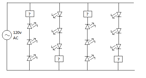
The box with the question mark is what I am assuming is some sort of current regulation mechanism.
So I decided the best thing to do was to simply increase the frequency from 60Hz to something high
enough where it wouldn't be annoying anymore. With no research into human eye flickering perception,
I blindly decided 500Hz was probably reasonable.
I decided to design the circuit in three stages: 1) The power subcircuit to provide +120v DC power
2) The oscillator subcircuit to provide a 500Hz square wave. 3) The drive subcircuit to take the
oscillator signal and use it to drive the christmas lights.
I found that my little christmas light string used 10mA RMS of current and decided I wanted my circuit
to support 100mA RMS.
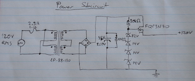
----- Power SubCircuit -----
 The power circuitry had the single most expensive ($15 from mouser) and massive component of my circuit.
A 130mA transformer to go from 120v to 88v, which I explain below. The only reason I went with this
component instead of some other sort of AC-DC/AC-AC converter is because I simply feel more comfortable
using transformers. Had this been an actual production circuit, this would probably be the first thing
I would redesign, replacing it wiht some sort of SMPS topology.
The power circuitry had the single most expensive ($15 from mouser) and massive component of my circuit.
A 130mA transformer to go from 120v to 88v, which I explain below. The only reason I went with this
component instead of some other sort of AC-DC/AC-AC converter is because I simply feel more comfortable
using transformers. Had this been an actual production circuit, this would probably be the first thing
I would redesign, replacing it wiht some sort of SMPS topology.
Since i was going to create a 120V square wave I would need 120v line. My plan
was to use a transformer to bring the AC voltage down from 120V RMS to about 83V RMS. This would give me a peak
of about 120v (83*sqrt(2)). I could then rectify and capacitor filter the transformer output to get my
+120V dc line. My christmas lights seem to
work fine down to about 100V and I wanted to support 100mA of current. I would need a capacitor such
that at 100mA of current my capacitor would only drop from 120v to 100v from one rectified 120v peak
to the next (8ms). Using C dv/dt = i and plugging in dv=20V, dt=8ms, and i=100ma
I got that my capacitor needed to be at least 40uF. I found a 47uF 250V unit at my local Fry's and
purchased that.
Once I soldered the circuit I realized I had made a very novice mistake. My transformer would convert from
RMS 120v to RMS 88v only when it was loaded with 130mA. At 10mA my transformer barely lowered the voltage
to RMS 110V, leaving me with a peak on my capacitor of 160V. I didn't want to buy or order new parts, so
I decided on the spot to add on a linear regulator in the form of a bunch of zener diodes to give me about
120V and connecting that to a power NMOSFET. I calculated the power dissipation of the nmosfet at 10mA and
100mA load (assuming at 100mA load the transformer voltage would drop) and I decided I wouldn't
need a heatsink for it. Unfortunately this would mean that at low loads I would lose a lot of power
to this linear regulator. Oh well.
I added a 1Mohm bleeder resistor in parallel to the 47uF capacitor because I didn't want to get zapped while
working on my circuit. A 1Mohm resistor gave me an RC time constant of 47 seconds to discharge to roughly
1/3 of its initial voltage, which worked for me.
----- Oscillator SubCircuit -----
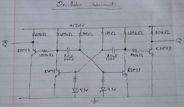 For the Oscillator I was deciding between using an astable multivibrator or a 555 based circuit. Ultimately
I decided they were both doable, and liked the idea of the astable multivibrator. I realized I probably
wouldn't be able to control the oscillations very precisely, but for my application I didn't care that much.
For the Oscillator I was deciding between using an astable multivibrator or a 555 based circuit. Ultimately
I decided they were both doable, and liked the idea of the astable multivibrator. I realized I probably
wouldn't be able to control the oscillations very precisely, but for my application I didn't care that much.
In my circuit the two "outside" transistors are used to drive the Q and /Q signals between 0v and 120V,
the "inner" ones are part of the astable multivibrator.
Most astable multivibrators online are setup for voltages below 12V. Running at 120v means that the "inner"
transistor bases needed to be limited to their minimum ratings, otherwise during the capacitor discharge
to ground the "inner" bases could theoretically drop to -120V for a very short time. The diodes limit them to about
(-4.3v)+(-0.7v) = -5v.
To minimize power loss I chose the "inner" resistors to be 1Mohm. The zener reverse leakage current was about 20uA
at -2v. My 1Mohm resistors would be pulling up about 100uA of current regardless of voltage, and I decided to
ignore the diode leakage currents for my calculations (meaning my clock would be running a little faster in my
product than i calculated for, not a big deal)
I need the time taken to charge either of the capacitors from -5 to 0.7V to be 1/2 the period I am aiming for.
At 500hz my period is 2ms, half that is 1ms. Using i= C dv/dt we plugin dv=5.7V, dt=1ms, i=100uA. C=17.54 nF.
I had two 20nF 1kV capacitors lying around, so I used those. The 180kohm resistors charge up the capacitors
to +120v (although in operation they don't actually get to 120v). The capacitor was charging too slowly to
create a nice square wave. Using values smaller than 180kohm didn't help too much, so it seemed to be
limited by speed that the "inner" bases were charging at. Because of this, I decided to use the "exterior"
transistors to amplifiy/sharpen the oscillations with 80kohm resistances. This gave me nice square waves at
the Q and /Q outputs. All of my transistors are operating, lightly, in saturation mode since I'm basically
just using them as on/off switches. I'm losing a little bit of power here but it shouldn't be much.
----- Driver SubCircuit -----
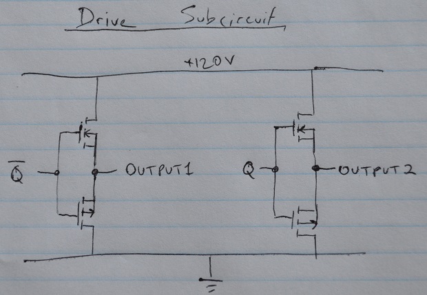
The last subcircuit is fairly simple. The Q and /Q outputs from the oscillator are taken and used to drive
the OUTPUT1 and OUTPUT2 outputs, which are connected to the "neutral" and "live" connections to my
christmas lights (although neither is now actually "neutral" or "live", they are both live voltage isolated
connections). I use power MOSFETS with the source connections connected together and used as outputs.
This means there is a voltage drop across the transistors where there is a small power loss. It also
means the output voltage is free to float a couple volts as long as its within the Vgs thresholds of both
the NMOS and PMOS. For my needs this is satisfactory.
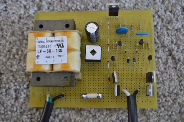
===== Final Results =====
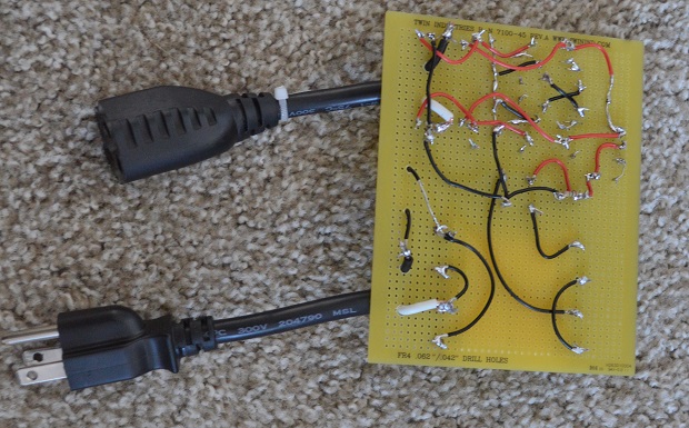
Below is the final product:
And here are the two outputs from my circuit (horizontal time units are .5ms):
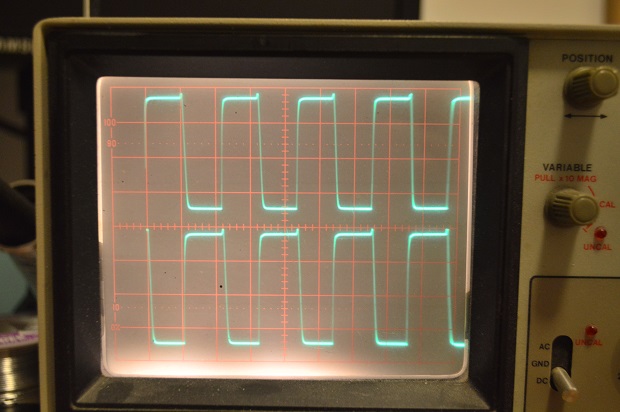
As you can see my oscillations are just under 1kHz, which works fine for me.
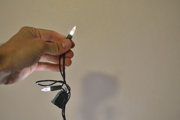
Here are my christmas lights connected to the circuit.
Below i demonstrate the flickering seen with 60hz LED christmas lights (first image), and
then I demonstrate the flickering seen with LED christmas lights running just under 1kHz (second image).
The images are shot with a 1/2 second exposure on a camera with me trying to move the christmas lights passed
the camera with the same speed for both shots.
60hz:

under 1kHz:

In practice the lights look much nicer at higher frequencies. The flicker is visible if you move your
eyes or the lights quickly (the same way that it's visible with the camera with long exposure). However,
the flicker is not perceptible when you are just looking at them unlike when you look at 60hz LED lights.
I did some simple load power measurements by measuring current with a multimeter through a 10kohm load
and 1kohm load connected
directly to the wall outlet and connected through my circuit.
| 10kOhm load current (mA RMS) |
1.17 kOhm load current (mA RMS) |
|
|---|---|---|
| Direct Outlet | 8 | 85 |
| My Circuit | 24 | 80 |
In this section are projects I completed working at Mosaic Industries Inc. We provided single board computers and my job included multi-tasking embedded programming, circuit debugging, soldering, website/domain/linux administration, and customer support. Unfortunately, the owners got tired of competing in the industry and R&D (me) was laid off January 2018. I enjoyed working there.
One of the products that we created for our single board computers was the EtherSmart wildcard.
This card expanded the functionality of our products by adding ethernet capability.
The drivers for this card supported having an HTTP and a websocket server. This was very convenient
for customers as it allowed them to interface with our single board computer using any modern browser.
See the "Web Advertisement" project below to see it in action.
Websocket is a transfer protocol
that is designed to be compatible with HTTP servers. It came around because HTTP is designed around the idea
that a client (the browser) initiates a connection and requests a file or data and the server delivers it.
After that the connection is closed and further communication requires starting a new connection. This is
very inefficient if you need to transfer data periodically. It's even more awkward if the data transfer
needs to be initiated from the server.
Websocket is more like TCP/IP. It allows either the server or the client to send data, and the connection
is left open. Modern browsers support websocket which means you can interface directly with websocket servers
using javascript. This makes for very convenient data transmission through the browser. When websocket
was announced it only supported sending text data.
PROBLEM 1
There were two problems I had to deal with in our EtherSmart Wildcard.
The first problem was revealed when a customer
called in to report that his single precision floating point values were not updating fast enough
using websocket. He sent me a wireshark capture that revealed he was using 18kb/s.
The engineer who designed the EtherSmart wildcard let me know that
this was roughly the maximum throughput that the EtherSmart wildcard would support.
My predecessor decided to use websocket combined with JSON to send data between our single board computers
and the browser. JSON is a method for sending data where you specify the attribute or variable name and
then specify the value. JSON uses text based data.
Here are all of the problems with this implementation:
My boss asked that I create a video advertising the interfacing
solution that we had created.
I decided to use open-source editing tools and settled on Blender
to do video editing, audacity to perform any audio work, and GIMP for
images/text/animations. I
also discovered that a lot of gaming "streamers" use an open source tool called
OBS to capture their gaming sessions. This tool was useful in
capturing my screen into video.
I captured the video on my boss's 480p camera and recorded
the audio separately using a $5 computer microphone. The camera
had its own mic, but the audio was lacking in any lower frequencies.
I synced the audio separately in Blender.
Despite the computer mic having better quality, i found that once I had
finished recording I had two types of audio files. One set sounded good,
and the other set had a low frequency buzz throughout the audio. I
remembered that the mic was hooked to my laptop and sometimes I connected
to grounded plugs and sometimes ungrounded. Maybe I was getting 60hz AC buzz.
I loaded up the audio in audacity and brought up the spectrogram functionality.
Sure enough, all of my bad files had noise right at 60hz.
Audacity gives options to filter out particular frequencies with varying roll-off
rates. I chose a narrow filter and removed the 60hz and my audio files all sounded much
better. Audacity also has a real nifty "noise-removal" tool that cleans up your
audio after it listens to the quiet parts of your file.
These are projects completed from 2013-2015 at UC Santa Cruz.
eMMC flash memory controller designed in Verilog (report).
This was my senior design project that my team and I completed for Oracle. The project
was to design a hardware controller in verilog to interface between a C driver and eMMC
memory chips. I did a lot of work planning the interface between the C driver and
our controller as well as doing a lot of testing and designing on the timing between
our controller and the eMMC memory (eMMC can run up to 200 MHz and can operate in
DDR mode, which means it can send/receive data on both the rising and falling edge
of the clock signal).
Our original design had the controller handling initialization as well as error handling.
The eMMC memory was directly memory mapped into memory address space of the Zynq
processor we were using (Zynq is Xilinx's Soc with an ARM processor and an FPGA). Since
the memory of eMMC could far exceed the local address space we were going to implement
a windowing scheme that would allow us to select a "window" of eMMC memory that we could
address at any point in time (think segmented memory from the old x86 days).
Later we decided these were all making the overall hardware design too complex, which
would both make design/testing complex and create a larger overall chip design (in case
the design would ever be put into silicon). A new design was created that would transparently
send and receive eMMC commands and responses to and from the software. All initialization
and error handling would be done by the C driver, not the chip. Furthermore, Oracle convinced
us that the memory windowing scheme would not be effective for a storage device. Instead,
specific memory addresses were chosen that would represent an eMMC command to send/receive,
an eMMC address, and data. This was good for us anyways, as creating a transparent hardware
controller meant using our original addressing scheme would be quite strange.
This project was also the first time I understood why my professors kept emphasizing how
critical timing and having nice clean clocks can be. There were numerous issues in debugging
the controller-eMMC interface, most of them had to do with seeing clocks that were far from
the nice looking square clocks they showed us in class most of the time. Trying to send data
using DDR (double data rate: rising and falling clock edge data transmission) certainly didn't
help things. Even though Xilinx provides dedicated input output drivers and logic designed to
handle DDR, it was still difficult to get it working. Eventually we settled on a particular
DDR method as well as using two different clocks. The clock we sent to the eMMC chip was
90 degree phase shifted which allowed the eMMC memory and our controller to capture on the "eye"
of the data. There were still some quirks with our design that I assume come from running at
frequencies in the MHz range, but the project came to a close before I could do more testing.
This began as an assignment for the graphics programing course at UCSC to create some
interactive sierpinski triangle in webGL. The vertices can be dragged around and the
triangle behaves with "rubbery" physics. This was my attempt at implementing spring
physics. Each vertex is connected to its neighbor vertices by a virtual spring. Each
vertices position is updated based on 3 things: current velocity, acceleration from
spring forces, and acceleration from dampening forces. Acceleration from spring
forces is calculated based on a change from the springs rest distance, which is
calculated at the very beginning. Acceleration from dampening is calculated by
multiplying the vertice's current velocity by some negative coefficient. Because the
dampening factor is based on the vertices speed, this dampening effect behaves like
the triangle is in a fluid. When I was first designing the triangle, this is actually
not what I wanted. I wanted the natural dampening force from any spring (like shocks
in a car). I didn't give this much thought at the time, and looking back on it now
I realize I would have to take the difference in velocity between one vertex and its
neighbor to achieve the effect I wanted. The effect I achieved impressed me anyways.
This also began as an assignment for the graphics programming course. Normal mapping
is a process by which surface "angle" information (represented by a normal vectors)
for a model is stored as a 2d mapping and processed in the same way as a regular
texture map is in the graphics pipeline. Surface angles are one of the three components
required in calculating how to calculate the lighting of some surface The other two
components are angle and distance to light source and angle and distance to camera.
Once we learned how to do texture mapping
(and we had already learned about the basic ambient/diffuse/specular lighting model)
I immediately realized I had all the tools I needed to implement normal mapping. The
effect of normal mapping can be seen in the link by the little details showing up in
the various textures that react to light as if they were 3d. However, make no mistake,
the floor is geometrically completely flat, and the rotating sphere is just that, a
sphere, and has no detailed depth to it.
cmpe100 final project (youtube video)
This was an FPGA project for the beginnig logic design course. All of our projects in
this course were crafted using the schematic editor in Xilinx ISE. It wasn't until
later that I learned how awesome Verilog is. The assignment was to create a
"Flappy Bird" look alike. However, the original assignment requirements had the bird
going up and down with constant velocity, which wasn't faithful to the original game.
In class I overheard some students half joking about how we should implement some
acceleration from gravity. Initially this seemed too difficult to do, but some more
thinking made
me realize that the vertical velocity of the bird can be implemented by some value
being added to its current position (1st derivative) at some regular interval. I
reasoned, then, that the acceleration can be implemented by some value being added to
the velocity value (2nd derivative) at some regular interval. Thus I decided to
implement a second mode in my assignment that was more faithful to the original game.
This second mode can be seen at the 1:05 mark in the youtube video.
When I finished
the project I was already running late on time, however, it was very obvious to me
that I needed some sort of a button filter because trying to click the jump button
once would sometimes cause the bird to jump multiple times in a fraction of a second.
The push button basically wasn't always making contact when the user pressed it,
instead introducing a lot of high frequency noise that made my bird jump multiple times.
Later, in my verilog class, I learned you can create an effective button filter by
sampling the button at some rate and adding or subtracting a counter if the button
is pressed or not and checking if the counter has passed some "boundary" value to
determine if the button is actually being pressed or not. You can also add some
hysteresis by creating two boundary values, one boundary value must be passed if the
button is to be registered as "on" but is currently registered as "off" and a different
boundary value for the opposite situation.
PSOC5 microcontroller final project (youtube video)
Report
main.c C file
connect4UART.h C header file
connect4UART.c C file
This was a project in our micro-controller course. We had to design a connect 4 game on
the PSOC5 system using an LED matrix and connect it to other students' boards through
UART so that we could play with each other. One technical problem I remember having
was getting a nice looking display with the LED matrix.
The LED matrix we had allowed us to control the colors on the LED matrix of every light
in a single row or single column. In order to create the appearance that the entire LED matrix
was lit and each light had independent control we had to implement a multiplexing system
that would light up a single row and then switch to the next row and the next row very quickly
so that it was imperceptible that only one row was actually being shown at any given time (like
a scanning CRT display). To minimize the number of pins needed I also implemented a couple
of shift registers that allowed me to serially shift out the color, row, and column data.
The cypress PSOC5 chip gave us the flexibility of implementing
this logic in software or hardware (the PCOC5 has a small amount of reprogrammable hardware
blocks).
I originally wanted to implement this in hardware since it seemed like timing would be
important to get a nice smooth LED display and doing precise timing in software can be tricky.
However, my professor persuaded me that it should be implemented in software since hardware
resources in general can be pretty limiting and we should conserve them and also because
doing things in software is typically easier.
I decided to follow my professor's advice and implemented the LED logic in software.
I had a main loop in my logic where all of my game logic was constantly being processed
and I put the LED logic in this loop. I had a separate timer interrupt that would flag
that the current LED row should be incremented. Unfortunately,
my system had various other interrupts and the main FOR loop had numerous other tasks
it needed to do besides refreshing the rows. Because of this, my LED display didn't look
very smooth, and instead seemed to flicker a lot.
As a test, I put all of the row refreshing
code I had directly into the timing interrupt routine. The difference
was obvious, where before I had flickering, now I had solid lights.
The interrupt routine with the test code had a small FOR loop and several function calls.
This is not ideal since interrupt service routines should generally be kept as small as possible,
but with my deadline approaching and with other priorities in the project I unfortunately left
it that way. Besides some minor things I wanted to fix, I thought my final product operated
quite nicely compared to other students.